Shock Response Spectrum (SRS) Analysis Solution
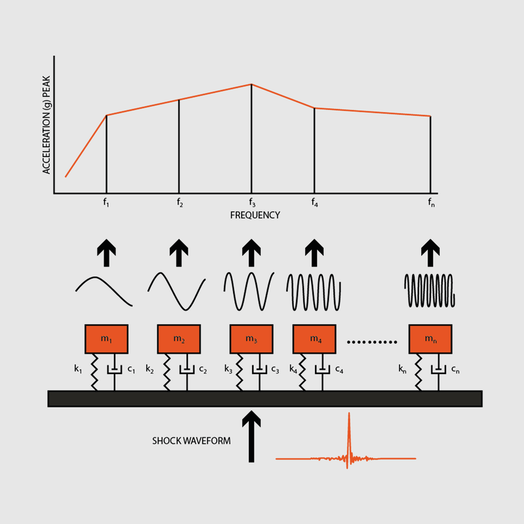
Mechanical shock pulses are often analyzed in terms of the shock response spectrum. The shock response spectrum assumes that the shock pulse is applied as a base input to an array of independent single-degree-of-freedom systems. SDOF system assumes that each system had its own natural frequency.
Mechanical shock pulses are often analyzed in terms of the shock response spectrum. The shock response spectrum assumes that the shock pulse is applied as a base input to an array of independent single-degree-of-freedom systems. SDOF system assumes that each system had its own natural frequency.
What is Shock Response Spectrum (SRS)
A Shock Response Spectrum (SRS) is a graphical presentation of a transient acceleration pulse's potential to damage a structure. The horizontal axis shows the natural frequency of a hypothetical Single Degree Of Freedom (SDOF) and the vertical axis shows the peak acceleration which this SDOF would undergo as a consequence of the shock input.
A shock response spectrum is a useful tool for estimating the damage potential of a shock pulse, as well as for test level specification.
The shock response spectrum is a calculated function based on the acceleration time history. It applies an acceleration time history as an excitation to an array of single-degree-of-freedom (SDOF) systems. Each system is assumed to have no mass-loading effect on the base input.
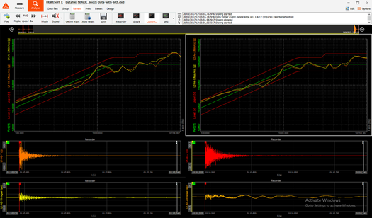
Shock Response Spectrum (SRS) Analysis & Calculations
Start Frequency and End Frequency: Define the calculation range for the frequency spectrum. The upper limit is set to 2000 Hz.
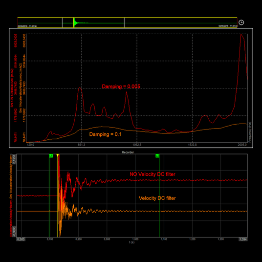
Velocity DC Filter: Removes the DC component of the calculated time signal.
Remove DC Offset: Removes the DC component of the input time signal.
Noise Floor: Calculate the noise floor of the input time signal.
Frequency Division (octave): Removes the DC component of the calculated time signal.
Damping/Quality Factor: Different damping factors produce different SRSs for the same shock waveform. Zero damping will produce a maximum response and very high damping produces a horizontal line.
Start Frequency and End Frequency: Define the calculation range for the frequency spectrum. The upper limit is set to 2000 Hz.
Velocity DC Filter: Removes the DC component of the calculated time signal.
Remove DC Offset: Removes the DC component of the input time signal.
Noise Floor: Calculate the noise floor of the input time signal.
Frequency Division (octave): Removes the DC component of the calculated time signal.
Damping/Quality Factor: Different damping factors produce different SRSs for the same shock waveform. Zero damping will produce a maximum response and very high damping produces a horizontal line.