High-Precision Power Quality Analyzer And Meter
Dewesoft Power Quality Analyzer can measure all the power quality parameters according to IEC 61000-4-30 Class A. In comparison to other power quality meters, Dewesoft systems are able to do more detailed power quality analysis. Raw data storing, behavior at faults, calculation of additional parameters, etc.
Dewesoft Power Quality Analyzer can measure all the power quality parameters according to IEC 61000-4-30 Class A. In comparison to other power quality meters, Dewesoft systems are able to do more detailed power quality analysis. Raw data storing, behavior at faults, calculation of additional parameters, etc.
Power Quality Overview
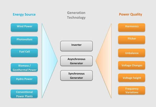
The different power quality parameters describe the deviation of the voltage from its ideal sinusoidal waveform at a certain frequency. These deviations can lead to disturbances, outages, lower power factor, or damages of electrical equipment connected to the grid.
The different power quality parameters describe the deviation of the voltage from its ideal sinusoidal waveform at a certain frequency. These deviations can lead to disturbances, outages, lower power factor, or damages of electrical equipment connected to the grid.
Dewesoft Power Quality Analyzer Highlights
Dewesoft Power Quality Analyzer is a very flexible DAQ solution that combines power and energy loggers as well as several other measurement instruments into a single device. This has multiple advantages for the measurement process:
Data Synchronization: data is fully synchronized and compatible for comparison
Raw data logging: raw data is always stored and therefore, can be analyzed at any time in post-processing
Easy to use: Intuitive software that can perform all the measurement and analysis tasks, meaning the learning curve is much easier to master
Low cost: a single instrument that can measure and analyze power parameters that would usually require multiple instruments will save space, time and money
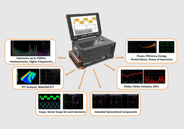
All of this combined makes Dewesoft power quality analyzer an indispensable piece of equipment that acts as an arsenal of devices able to measure among others:
Harmonics and THD up to 150 kHz
Interharmonics & Higher Frequencies
Flicker, Flicker Emissions, RVCs
FFT, Harmonic FFT, Waterfall FFT
Symmetrical components
Power Quality Standards Overview
Dewesoft Power Quality Meters fulfill all the requirements of power quality standards and can be used in a wide range of testing applications. The table below sums up the supported power quality standards:
Dewesoft Power Quality Meters fulfill all the requirements of power quality standards and can be used in a wide range of testing applications. The table below sums up the supported power quality standards:
|
IEC 61000-4-30
IEC 61000-4-7 IEC 61000-4-15 EN 50160
EN 50163 IEEE-519 IEC 61000-2-4 IEC 61400-21
IEC 61400-12 FGW-TR3 BDEW VDE-AR4105 IEC 61000-3-3
IEC 61000-3-11 IEC 61000-3-2
IEC 61000-3-12 |
Requirements for Power Quality Analyzers, Calculation of Harmonics, Flicker, etc.
Power Quality limits of the public grid, industries and railway applications.
Power quality analysis or renewable energy sources.
Electromagnetic compatibility (EMC) of voltage changes and Flicker.
Electromagnetic compatibility (EMC) of harmonics current.
|
FFT Harmonic Analysis
Harmonics are integer multiples of the fundamental frequency (e.g. 50 Hz) and cause a distortion in voltage and current of the original waveform. Harmonic voltages and current caused by non-sinusoidal loads can affect the operation and lifetime
of electrical equipment and devices.
Harmonic frequencies in motors and generators can lead to increase heating (iron & copper losses) can affect torque (pulsating or reduced torque), create mechanical oscillations, and higher audible noise, which can cause aging of shaft, insulation and mechanical parts and reduce the efficiency.
Current harmonics in transformers increase copper and stray flux losses. Voltage harmonics increase iron losses. The losses are directly proportional to the frequency and therefore higher frequency harmonic components are more important than lower frequency components. Harmonics can also cause vibrations and higher noise. The effects of other electrical equipment and devices are very similar and mainly reduced efficiency and lifetime, increased heating, malfunction or even unpredictable behavior.
Full FFT Frequency Spectrum Analysis
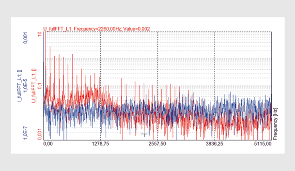
In addition to the FFT harmonics, a full frequency-based FFT analysis is available. All frequencies can be analyzed with this function Trigger on FFT patterns and offer definable filters:
Hanning / Haming / Flat Top / Rectangle / etc.
In addition to the FFT harmonics, a full frequency-based FFT analysis is available. All frequencies can be analyzed with this function Trigger on FFT patterns and offer definable filters:
Hanning / Haming / Flat Top / Rectangle / etc.
FFT Waterfall Analysis
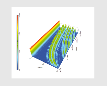
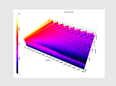
Besides the FFT and the harmonic FFT analysis, the Power Quality Analyzer also offers a 2D and 3D FFT waterfall analysis option.
This type of data visualization is especially useful for the analysis of variable drives. For example, looking at a run-up of an inverter, it is clearly visible how the harmonic sidebands originate as the frequency increases. The image depicts the run-up of an inverter of a traction drive from 0 to 150 Hz.
The FFT waterfall visual display can be linear or logarithmic, 2D or 3D and sorted by harmonic order or frequency.
Flicker Test & Flicker Emission Test
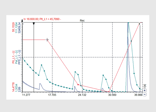
Flicker is a term used to describe fluctuations (repetitive variations) of the RMS voltage between two steady-state conditions. Flashing light bulbs are indicators for high flicker exposure. Flicker is especially present in grids with a low short-circuit resistance and is caused by the frequent connection and disconnection (e.g. heat pumps, rolling mills, etc) of loads that affect the voltage.
A high level of flicker is perceived as psychologically irritating and can be harmful to humans.
Dewesoft Power Quality Analyzers offer the following features for flicker measurement:
Measure all flicker parameters according to the IEC 61000-4-15 standard
Flicker emission calculation according to the IEC 61400-21 standard and allows the evaluation of flicker emission into the grid caused by wind power plants or other generation units
PST and PLT with flexible intervals
Individual recalculation intervals
P(inst.), d(U), d(Umax), d(Uduration)
Rapid Voltage Changes
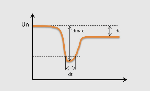
Rapid Voltage Changes (RVCs) are parameters which are added as a supplement to the flicker standard. Dewesoft data acquisition software calculates these parameters according to the IEC 61000-4-15 standard.
Rapid Voltage Changes describe any voltage fluctuations which change the voltage amplitude between two steady states more than 3% for a certain time interval. These voltage changes can be analyzed in post-processing using various parameters:
The depth of voltage change / d(U), d(max), d(Uduration) / Steady-state deviation / Etc
Unbalance - Symmetrical Components
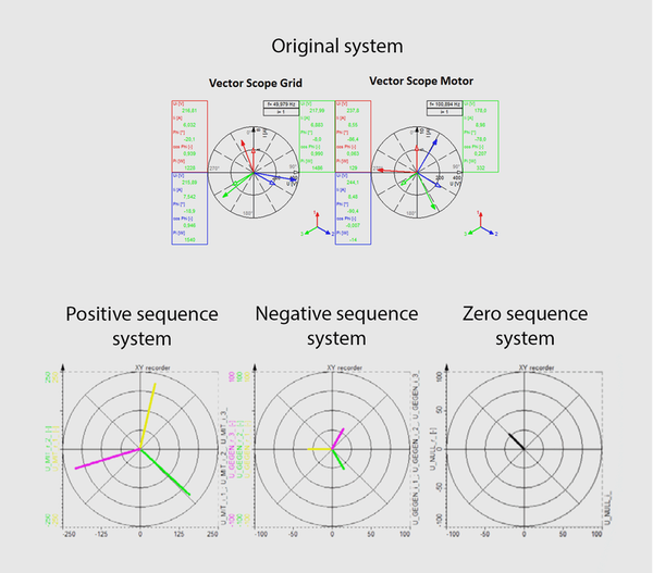
A balanced system has a 120 deg phase shift between the voltages and currents, and the voltages and currents have the same amplitude respectively. Unbalance happens when the 3-phase system is loaded unevenly and the phases and magnitudes no longer correlate.
To analyze an unbalanced system, the symmetrical components calculation method is used. This method splits the original unbalanced 3-phase power system (rotation like the original system), the negative system (rotation in the reverse direction) and a zero system.
An unbalanced system could cause current to flow in the neutral line, overheating electrical components, mechanical stress, increased vibration, and torque pulsation, low power quality and energy losses among others.
Dewesoft's Power Meters can measure over 50 parameters for a comprehensive analysis of an unbalanced system. These parameters include various calculations for voltage, current, active-, reactive-, apparent power as well as harmonics.
Frequency Deviations
Dewesoft Power Analyzer can be used for frequency monitoring and testing frequency behavior of power generation units in the developmental stage.
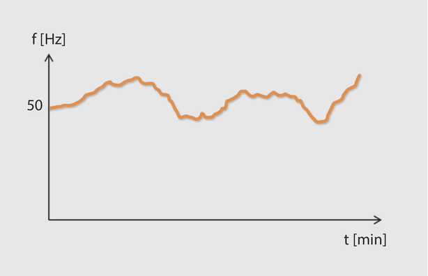
High-frequency deviations from the fundamental frequency in public grids can have severe consequences. If the frequency drops or rises excessively there is a chance that the whole power system could collapse causing a blackout.
Frequency deviations in power grids are caused by the connection and disconnection of power generation plants or big loads. The grid becomes unstable if there is a deviation from the nominal frequency at which the grid operates. If the frequency is too high, there is too much power in the grid due to power oversupply. If the frequency is too low, there is too little power in the grid due to power under supply. As renewable energies especially, wind and solar become more popular, grid stability is more at risk than ever. This is due to the fact that wind does not always blow at constant speeds and that sun energy gets impacted by clouds, shadows and fluctuations in radiation intensity. This leads to abrupt deviations in the frequency at which power is delivered to the grid.

