Modal Testing & Modal Analysis - SIMO, MIMO and ODS
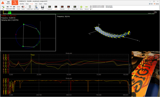
Effective and affordable modal testing and analysis solution for SIMO, MIMO and ODS testing methods. The modal test is an indispensable tool to determine natural frequencies and mode shapes of any structure. With Dewesoft solution, you are able to excite the structure with an impact hammer or modal vibration shakers and easily measure the responses. Import or draw your geometry for rich visualization and animation of your structures.
Effective and affordable modal testing and analysis solution for SIMO, MIMO and ODS testing methods. The modal test is an indispensable tool to determine natural frequencies and mode shapes of any structure. With Dewesoft solution, you are able to excite the structure with an impact hammer or modal vibration shakers and easily measure the responses. Import or draw your geometry for rich visualization and animation of your structures.
Multi-Input Multi-Output (MIMO) Calculation
MIMO measurement techniques are a well-proven and well-established method for collecting FRF data sets. They offer some distinct advantages for the measurement and extraction of basic modal parameters especially while testing larger structures.
The main advantage of MIMO is that the input-force energy is distributed over more locations on the structure. This provides a more uniform vibration response over the structure, especially in cases of large and complex structures and structures with heavy damping.
Excitation in more locations often also provides a better representation of the excitation forces that the structure experiences during real-life operation.
Easy & Quick Setup
In the case of a high number of measured channels, adding and removing the excitation and response channels is a very simple process with autofill setup.
Autofill functionality is enabled for:
Autofill for uniaxial and triaxial sensors (response channels)
Start node index and index increment selection
Define the direction and sign of added channels
Group the sensors and define the number of groups
Auto-generated Visualization Screens
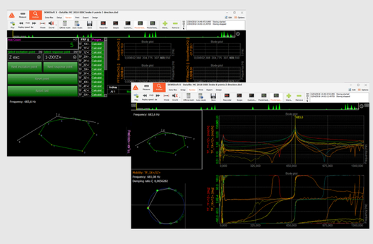
For an easier start, Dewesoft software offers auto-generated displays for modal analysis. The predefined display already come with the most often used instruments and an arrangement that makes sense according to the modal testing.
One screen is generated for the acquisition and measurement process and the second screen is defined for the post-analysis of the measured data.
Of course, the flexibility of Dewesoft data acquisition software allows you to easily change and customize the default displays or define unlimited new ones.
Structure Geometry Animation & Projection
Inside Dewesoft DAQ software, you can quickly draw simple 3D structures as well as import more complex ones using UNV file format. The cartesian and cylindrical coordinate system is supported, which is great for drawing circular objects.
You can animate the structure at a single frequency in all three directions. During the measurement, the color of the points is changing, for easier identification of the excitation point and the response points.
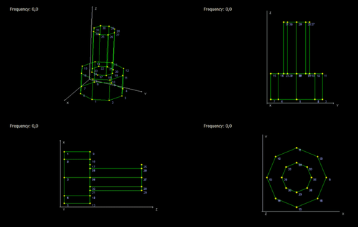
The structure can be shown in different projections:
3D perspective / 3D orthographic / Several 2D projections
Merge Multiple Data Files Together
Dewesoft software makes it very easy to record one data file for each point or group in your subject under the modal test.
After the measurements are done, you can easily merge separate data files into one to analyze and animate the structure and observe the behavior.
Each transfer function contains information about response, node, response direction, reference node and reference direction.
Operating Deflection Shapes (ODS)
In ODS analysis, the structure is only excited by the machine, like in real operation, whenever it is not possible to vary the excitation frequency. ODS is the simplest way to see how a machine or structure moves during its operation at a specific frequency.
Dewesoft software modal test module, one of the acceleration sensors has to be defined as excitation (this one is the reference, normalized to 1), and others as a response. Animation can be displayed as usual but only makes sense in areas with good coherence.
OMA - Operational Modal Analysis
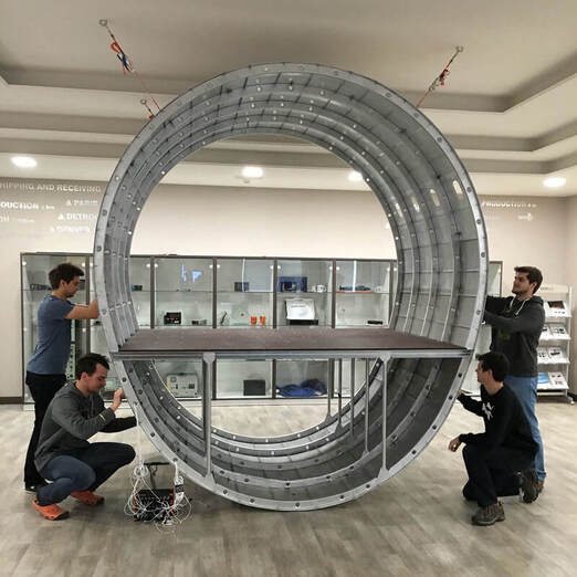
The operational modal analysis is used for large civil engineering structures, operating machinery, or other structures, making use of their output response only. These structures are always loaded by natural loads that cannot easily be controlled and measured, for instance wave load (offshore structures), the wind loads (buildings) or traffic loads (bridges).
Dewesoft can be used to perform all the necessary time-domain measurements which can be exported to various file formats in order to make calculations in external software (e.g. ME' scope)
Exporting Data
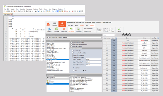
After the measurement is done the data can be exported to a lot of different file formats, e.g. UNV/UFF, Diadem, Matlab, Excel, Text...The transfer function can be separately exported by Real. Imag, Ampl or Phase part.
The Universal File Format (also known as UFF or UNV format) is very common in modal analysis. Depending on the header, it can contain either transfer functions, coherence, geometry, ... or various other data. We modified the UNV/UFF export, especially for the modal test.

